Electrical
control panel design basics are
simple. Cost is always important, but so are an attractive appearance,
simple operator controls and reliable operation. A simple panel
design is less expensive to
produce, uncomplicated to
operate and easier to maintain.
When
you specify a control panel’s design requirements, it helps if you understand
that control panel design is a
process. Before you start the process you may think you know exactly
what you want. After you start the process your ideas may change.
When
you first put your panel design requirements on paper they seem unorganized.
This is normal because no one gets everything right in one pass. Design is a
process and it takes time to get
it right.
Rewrite your requirements until
they’re properly organized and clear. Understand what you want, write it
down using clear language, and then proceed with the actual hardware design.
Step 1
• start physical
Don’t
shortcut the design process and produce schematic drawings without producing
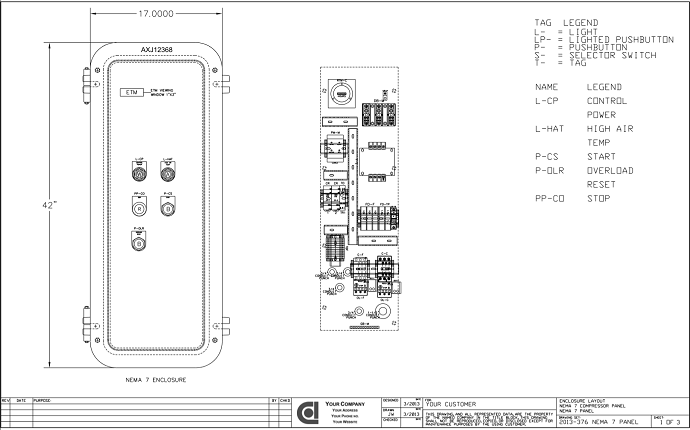
physical layout drawings. Good control panel design includes physical and electrical requirements.
Experienced control panel designers alternate between the physical and
electrical until all potential problems have been solved.
Good control panel designers include
National Electric Code (NEC) required clearance around power wiring and
Underwriters Laboratories (UL) required clearance around heat producing
devices.
·
NEC requires bending radius
clearance around incoming and outgoing power connections to insure the
installing electrician has adequate room to make their power connections,
·
UL requires manufacturer recommended
clearance around heat producing devices (Programmable Logic Controllers,
Variable Frequency Drives, etc.) to insure for adequate room for ventilation.
Step
2 • coordinate wire sizes and component types

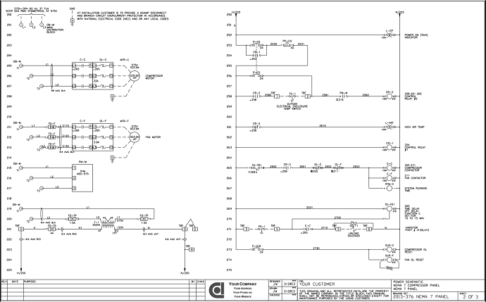
Good control panel designers select
components based on voltage and load current and component type based on
function. The correct component size insures it can reliably handle the
required voltage and load current. The correct component type insures
it’ll function as desired.
Step
3 • use the best control type
Experienced
control panel designers always start
with simple control components (Relays, Timers, etc.) When
simple doesn’t get the job done, they’ll use something with more functionality
like a programmable Smart Relay or a Programmable Logic Controller (PLC). These
provide significantly more functionality, but they also require a computer
and programming software and someone who knows how to use the software to
program the desired functionality.
Some
control panel designers automatically start with a Programmable Logic
Controller (PLC). Sometimes a PLC is the way to go, but you should always use the simplest control
type appropriate to the application.
Step
4 • use the best operator device type
Experienced
control panel designers always start
with simple operator devices (Pushbuttons, Pilot Lights,
Digital Panel Meters, etc.). For a stylish appearance they’ll add a Color
Graphic door laminate. When simple doesn’t get the job done, they’ll use a
color touch screen display as the Human Machine Interface (HMI). This
provides significantly more functionality, but it also requires a computer and
programming software and someone who knows how to use the software to program
the desired functionality.
Some
control panel designers automatically start with a Human Machine Interface
(HMI). Sometimes an HMI is the way to go, but you should always use the simplest operator device type
appropriate to the application.
Step
5 • use the best in class products by category
Experienced
control panel designers use the best
in class products by product category. This is subjective
based on product awareness. Experienced control panel designers are aware of
the array of products available in a product category. This allows them to
compare and use products that provide the best balance of price, form and function.
Some control
panel designers try to use one manufacturer for all components in a panel.
European companies tend to do this and some US companies do too. Sometimes
there’s a reason why this makes sense, but generally it limits your
ability to use best in class
products by product category.
Comments
Post a Comment